Wednesday, February 20, 2019

Firmware changes and first prints

So I ended up applying all firmware changes except for the Y axis. This seemed to make only issues with the calibration and did not make any sense to me.

I have created a Github fork of the original Prusa code here and will upload my binaries as well.
But remember they are working for my printer with the Titan Aqua clone, use them on your own risk!

https://github.com/empusas/Prusa-Firmware

Now it was time to perform the first layer calibration. After hassle with the filament I noticed that the new(!) nozzle was blocked. So I had to take the hot end apart and replaced the nozzle. I heated up the nozzle again and now I could push filament thru.

I wanted to test the build plate stickers I got from Aliexpress, but unfortunately they are thicker than the Prusa PEI sheets. So I had problems to get the PLA lines from the sticker after the calibration as the nozzle was too close.
What is also irritating is that the stickers have the same markings as the magnetic heat bed. So just in case you think I am printing directly on the magnetic heated when you look at the photos,  be assured I am not.

So now it was time for the first print. I picked a small part to print and was successful with my standard Prusa MK3 profile.


Then I felt comfortable to perform a more sophisticated print. I changed the extruder steps per mm, so it was obvious to print the extruder linearity correction calibration object from Prusa.

https://github.com/prusa3d/Prusa3D-Test-Objects/tree/master/MK3/ECOR_TOWER

This tower is printed with a single parameter wall and changes the correction factor every few mm.
I took the Prusa G-code file without any changes and was surprised about the good result.
I need to deeply analyze the print to figure out the correct factor, but It shows already that I don't have any major flaws.


Now I wanted to print my first big objects. One reason is that I wanted to monitor how a printer over 10h performs. The other reason was that I wanted to see how much the temperature from the cooling water would rise during such a long print.
But I didn't want to print this one from SD card. So it was time to install the Raspberry Pi that I prepared in an earlier blog post.


The installation was easy and the octoprint server came up without any issues.


The first problem I encountered was that the steel plate was moving on the heat bed. Not sure if the distance is too big for the magnets because of the thicker stickers, or if the sticker on the backside of the steel sheet is too slippery. Anyway, I ended up securing the position with tape.

I even made some photos and a video. Like to see some first layer porn?


Remember the lines from the first layer calibration? That is what you see here.


Tuesday, February 19, 2019

Prusa, we have a problem!

Over the last days everybody was excited about the MK3S and MMU2S announcement from Prusa.
I took the time and looked into it deeper. And I am not amused!

So let's start with the extruder upgrade. Prusa replaced the filament sensor with a new one to overcome the issues with the MMU2 and some filament types/colors. But before I start mocking about the new MK3S sensor, let me explain how the old Mk3 version worked.

Prusa had developed an optical sensor that worked similar to an optical computer mouse. It could detect if filament was loaded, but also if the filament was moving. The PAT9125EL optical laser movement sensor had some issues with some types of filament and different colors. That led to false alarms for some users.
It seems like the tiny strings end the end of filament that can occur during the unload of filament increased the problems even further. Usually you just cut them off, but if you use the MMU2 this might not work for you.
But anyway, this was a remarkable innovation from Prusa. Things like this let me hold Josef always in high regards.


So, for the new MKxS extruder they changed the filament sensor completely. They still claim to have an optical sensor, but that is just a light barrier activated by a mechanic. There is a little arm pushed by the filament that then blocks the light in the forked light barrier. And hey, they are not using a spring, they use magnets instead to press the arm out of the fork.


With this new sensor you can still detect if filament is loaded or not, but you cannot monitor if the filament is still moving. So if your nozzle is clogged, that will not be detected anymore.


To me this was a step in the wrong direction. This kind of mechanical sensor is what we have seen before on some Chinese printers.  I do understand the pain with the MMU2, but come on, there would have been better ways so solve this.

There are plenty of designs that use a small ball bearing for indirect monitoring of the filament. The sensor then detects the movement of the bearing that is driven by the filament. As the bearing surface and color does not change, there is no problem with the glossy filament or different colors.
That would have been an improvement.

Let's see the MMU2S, what is new? Well, we don't really now. There is no MMU2S branch in Github and the MMU2 branch was not updated for 6 months as of today(Feb 18 2019).
All that was seen in the announcement was a photo of the new "Filament Buffer".


For those who don't know the MMU2. There is a problem when one filament is unloaded from the printer, it gets pushed back. In some cases the filament get interlaced with each other and create problems.
So people come up with solutions like those here:
https://www.thingiverse.com/thing:3241474
https://www.thingiverse.com/thing:3184377

And it seems to me like Prusa did come up with something similar. As the STL´s are not published yet, we cannot confirm. But it also seems like the filament is bended with small radius in there.
Depending on the filament this could lead to break bridle filament in here.

Besides the "upgrades",  let's talk about quality.
I used the feather steel build plate with PEI sticker from my original Prusa MK3 kit for about 12 month. I printed PLA, PETG, Nylon and even PC on it. But over time it got some scratches and I even ripped a pice off when I did not wait until it was cooled down when I removed a PETG part.
No big deal, because I ordered already a spare one for 24,99€.
It looked very different from my first one. No raster markings and the little notches on the back have been replaces with a long cavity. I don't care a long as the quality is ok.
And right after the first print, it ripped off a big chunk. I waited for it to cool down, and bended the steel sheet carefully. But Zonk!


Ok, not nice. I expected same quality as my first one, but ok. So I ordered 2 kits of PEI stickers for 9,49€ each to repair both original build plates. I need to admit that I did not read the details, so I was under the impression that I will get 4 stickers, 2 per kit. That made sense to me because if you try to replace one side only, the chances are high you mess up the other side anyway. So usually you would replace the stickers on both sides of the steel sheet.
To my surprise I got 2 stickers in total. So ~10€ for one PEI sticker, both sides is ~20€ then. That raised the question why go thru the hassle to remove the old sticker, clean the surface and apply the new ones with no air bubbles, when you get a complete one for only 5€ more?
I guess I should not have asked the Prusa support, because when I did the price for the complete build plate was raised to 29,99€. Fun fact, as of today, the powder coated version is still advertised with 24,99€. But still not in stock.

I already pointed out in an earlier post that Prusa charges you nearly 60€ for the LCD display plus shipping, that you can buy from Aliexpress for less than 8€, shipping included.

Also some other parts are quite expensive in the Prusa shop. But what is really annoying are the shipping costs. Sometimes the shipping costs rise to a ridiculous amount for small part like springs, nozzles etc. At least I got a 10€ voucher last time when I complained about at the support.

Prusament. Not sure where to start.
Last year I switched my PETG from local German vendors to Prusa because I had very good results with the PETG from Prusa. Also the price was reasonable with just over 20€ per 1Kg spool.
Then Prusa decided to produce their own filament. They advertise a lot with the precision and that you can track any process step by the serial number of the spool.
GREAT! For those people who need this, perfect. But for me this is absolutely irrelevant. I don't care about the process data of my filament spools and for the parts I print the tolerances of the old Prusa Filament was more than ok.
But as this is now made in house, I would guess production costs are cheaper than buying and reselling it from a vendor, right? Well, I don't know. Only thing I can see is that a 1Kg spool costs now 30€. Too much for my taste.
But there is still the option to buy the old filament fron Prusa right? NO
Prusa has removed all old PLA and PETG filament are you find only Prusament now.
Besides the increase in price, they don't even habe all the colors they had before.

Currently I am trying to buy directly from the company that made the filament for Prusa before, which is Plaste Mladic in Czech Republik.

http://www.plastymladec.cz/?id=1

To me all those things add up. The MK3 was not my first printer, I had some cheap chine printers before. They also did the job. But I wanted to support Josef Prusa and thank him for the innovation he brought to the 3D printing community then I decided to buy my MK3 kit and filament for couple hundred €. And honestly I was just think to buy another MK3.
But I am reconsidering this and maybe just build another clone with china parts.


Sunday, February 17, 2019

The angled cable holder. I got some requests to publish my angled cable holder.


So here it is https://www.thingiverse.com/thing:3433695

Tuesday, February 12, 2019

And compiled again.... XYZ calibration was a success this time!

I have to admit that was a little frustrated after I could not get the XYZ calibration to work. So this weekend I first wanted to rule out any mechanical problem.
I unscrewed the trapezoid nuts on the z lead screws from the CNC aluminium x-ends. Then I turned the Delrin nuts all the way up to the top of the z axis.
This way I could freely move the x-axis on the z-axis. I noticed some drag and the z-xis got stuck at some positions. This was truly a problem of the cheap Chinese bearings I used. I lubricated them with  white lithium grease before, but that seemed to make it even worse.
I should have cleaned the bearing in cleaning solvent before, but I was too lazy.
So the quick fix was to move the x-axis assembly up and down by hand, after some time the drag was nearly gone and it did not get stuck anymore.
Now I screwed the Delrin trapezoid nuts back into the alu parts and tried again.

This time it failed again on the XYZ calibration while it was searching the 2nd calibration point.

Now it was time to revisit my changes to the software. I pretty much took all the changes from Chris post on Thingiverse. I already had a suspicion that the changes on the Y-axis might be wrong, I will get into details once I have confirmed it.

So I started with a fresh copy the Configuration_prusa.h and made only one change to the z-axis limit. I changed the value for the Z_MAX_POS from 210 to 218.  And that was all, no other changes.
I did not even change the stall detection sensitivity for the z-axis.


So after flashing the firmware I was able to successfully complete the XYZ calibration. It worked like a charm.


So that proofed two things.
One, I had a mechanical problem on the z-axis and the motors from bluerolls are doing fine.
Second, there is something else wrong with the other changes I made to the software.

I will continue the testing on the weekend to figure out exactly the right values and what needs to be changed.

Saturday, February 2, 2019

Change and compile the original Prusa MK3 firmware

I was thinking of different ways to make the build of the Prusa Firmware easy for everyone. One idea was to build a virtual machine or a docker container with everything you need. But I noticed that the way Prusa describes by using the arduino IDE is the easiest, if you know what is not described in the Prusa ReadMe file.
By the way, I am using a Mac. I don't use Windows and cannot give you any platform specific help for Windows. But the tools and process should be the same.

There are different versions of the arduino IDE that you can download at https://www.arduino.cc/en/main/software .
There have been problems in the past and you might see people using the 1.6.x versions as they could not get it to work with 1.8.x. Even Prusa recommend to use "1.8.5".
But as far as I can say those problems are fixed. I could get the latest version (1.8.8) to compile the Prusa firmware without any issues.


Once you have installed the Arduino IDE, you need to install some definitions for the Prusa Einsy board. This is also described in the ReadMe from Prusa.
First you need to add the URL that should be used to fetch board definitions. Go to "Preferences" in the Menu and you get this popup window.


Under settings there is the entry "Additional Board Manager URLs". When you click on the icon right next to the text field a new popup window appears.


Add the line "https://raw.githubusercontent.com/ultimachine/ArduinoAddons/master/package_ultimachine_index.json" to the list and click ok. Then click ok on the previous window.
As you can see from my screenshot I do have another Prusa entry in my list, this is what you need for the MMU2 board, not for the Einsy Rambo.

When we navigate to Tools->Board->BoardsManager a new popup window will open.


Select the "RepRap Arduino-compatible Mother Board (RAMBo) by UltiMachine" in the latest version (1.0.1 as I am writing this guide) and install it.
Again you see the Entry from Prusa research in my list, this is for the MMU2 board, not the Einsy Rambo.

The next step from the Prusa ReadMe says you should change the compiler flags in the "platform.txt" file. Many people fail here because they don't know which file to change, then they search and find, depending on the platforms installed in the arduino IDE, many "platform.txt".

c. modify platform.txt to enable float printf support:
add "-Wl,-u,vfprintf -lprintf_flt -lm" to "compiler.c.elf.flags=" before existing flag "-Wl,--gc-sections"

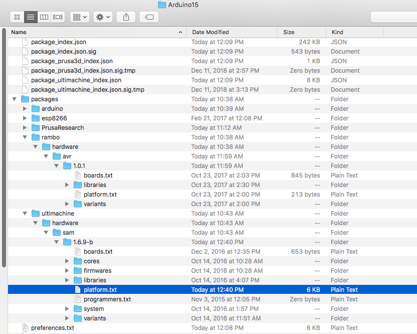
First go to the arduino IDE main folder. If you don't know how to get there, go to preferences in the menu, there is a line "" click on it and the folder will open. But make sure you close the arduino IDE while you are editing those files!


But if you look at the "platform.txt" file that is in the Rambo folder, it does not contain anything like the line you should change.


Next you open the ultimachine folder and edit this "platform.txt".


You find the line and add the "-Wl,-u,vfprintf -lprintf_flt -lm" to it. That should work right?


NO, it does not!

When you compile the code will get no errors, but the firmware will not work properly. You can easily spot this problem on the Prusa start screen when you have flashed a firmware with those flags not enabled. The z height is showing a "?" instead of a value.


The only place the compiler changes worked for me are in the arduino->hardware->avr->[version] folder.


Edit the "platform.txt" in here as described in the ReadMe and it will work. I did for me at least.


Save the file and when you start the arduino IDE next time this is active.

Hint! With every arduino IDE update this will be overwritten and you have to edit it again. Or create a "platform_local.txt" for persistent changes.

Now that we have setup our environment to compile the code, we need the code itself.
As Prusa publishes everything as open source on GitHub we can get the code from there.
https://github.com/prusa3d/Prusa-Firmware

If you are not familiar with Git and have no Git or Git Desktop installed, the easiest way to get the code is to download a zip file.


In that zip file is all the code you need.


The next step is to copy the file "1_75mm_MK3-EINSy10a-E3Dv6full.h" from the sub directory "variants" to the enclosing directory "firmware" and rename it to "Configuration_prusa.h".


Now we are prepared to make modifications to the code. Please us an editor that does not change the format of the files. On Mac the TextEdit works fine, other tools might transform the files in some rich text format which makes them unusable. Be careful if you use Windows, Windows tools by default change the text format by adding a carriage return to each line. Get a tool like Notepad++ if you use Windows.
As you may see from the next screenshots I am using Eclipse, a developer IDE. You don't have to use Eclipse and if you don't know how to use it, it may be too difficult for you. I use it as I am used to it as I do other software projects.

Prusa recommends to disable multi-language support in the "config.h" file. I have no idea why they still have it enabled in the source files, if they recommend to change it. Just comment out( add "//" in front) the line the value "#define LANG_MODE 1" and uncomment (remove the "//" from the front) the line with the "#define LANG_MODE 0". You find those line pretty much at the end of the "config.h" file.


If you don't plan to make any other changes to the original Prusa firmware you are good to go now and compile the code. Maybe it is not a bad idea to give it a try now, while you have not changed anything. That could rule out any problem you could have made so far.


Ok, now we need to tweak some settings in the code. In my case I am not using the E3D V6 or a clone of it. Instead I am using a Titan Aqua Clone from China.
The nozzle from this different hot-end and mount is not at the same position as I would have used an E3D V6. The other changes we have to make are the extruder steps. Because this is a 3:1 geared extruder we have to change the steps per mm and the direction of the motor.

I am using the values that Chris Vahi posted on Thingiverse for this Titan Aqua mount. I remixed his mount for me as I wanted to have the hoses straight up from the hot-end. But I did not change any other geometry from his design. So in theory his values should work for me.

We need to modify the "Configuration_prusa.h" file that we copied and renamed before.
First we change the steps per millimeter for the extruder motor from the default 240 to 840. Look for the line "#define DEFAULT_AXIS_STEPS_PER_UNIT".

It is the last value in the line, I just commented out (//) the original and copied it to a new line with the new value.


Now we need to change the direction of the extruder motor. Find line "#define INVERT_E0_DIR".


The comment seems to be the opposite of what this line value does. So I changed it to "1".


The next step is to adjust the z axis. As the nozzle is higher as on the usual MK3 we have more z height. But as the nozzle is more towards the front of the printer, we have less space on the y axis for printing. Look for line "Travel limits after homing"


Then change the value for the z axis from 210 to 218 and for the y axis from 215.5 to 170.5. Everything else stays the same.


In my case the z calibration always failed, the motors did not move but kept humming. As Prusa does not use end stop switches, but rather the stall guard feature on the TMC2130 motor drivers I need to adjust the sensitivity for the z axis from 4 to 5. I guess the root cause is that the motor I git from bluerolls just need more current as the LDO motors that Prusa uses.


We also have to tell the firmware that the offset between the nozzle and the P.I.N.D.A probe is different now. Look for line "#define X_PROBE_OFFSET_FROM_EXTRUDER".


Then we change the value for the x axis from 23 to 30 and for the y axis from 5 to 45.


That is it for the"Configuration_prusa.h", you can now save it.

In the "Configuration.h" you find offset for the P.I.N.D.A probe as well. But they don't match with the values in the "Configuration_prusa.h". Seems like they are not used anyway. The whole section is an "ifdef" and the value "ENABLE_AUTO_BED_LEVELING" is commented out before.


For now this is all I want to change. Once I have tested the printer I want to implement some more enhancements to the code, like the 7x7 mesh bed leveling.

Now we can compile our code. Open the arduino IDE. Then go to File->Open and open the "Firmware.ino" file in the Firmware directory.


Then go to Tools->Board and select the RAMBo board.


Now you can go to Sketch-Verify/Compile to see if you can compile without any issues.


The compiler will now take a few seconds to verify and compile the code.


If that was successful you should see a message like this.


Then go to Sketch->Export compiled Binary and it will compile again and export the hex file we need.


Then a new file should appear in our firmware directory.


You may notice that the file size is smaller than the hex files you get from Prusa. The only explanation I have for this is that Josef Prusa mentioned sometime that they link the bootloader now together with the firmware.
This is why I would recommend to first install the latest Firmware from Prusa on any new board you get from Ultimachine or chinese sellers.

The next step is to flash the firmware to the printer. I used Slic3r PE for it. It is exactly the same process as with every firmware update from Prusa.
Use the USB cable to connect your printer to the computer and turn the printer on.
Go to Configuration->Flash printer firmware in Slic3r PE.


Open the file and hit rescan if you cannot see the printer detected.


Then hit Flash! and wait for the firmware to be flashed to the eeprom.


Once it is completed you printer will reboot and you can close the popup from Slic3r.


So far everything looked well. First thing to check was if there is a proper value for the z height on the start screen. This proves that the compiler flags worked. Then I moved the axis around and everything seemed to work fine.


But I still have issues with the XYZ calibration. For some reason the first calibration point is found with no issues, but the 2nd one(front right) fails every time. Sometimes I had to hit the reset button as the nozzle was scratching on the paper. 
As you can see the sensor is about + 30-40 mm off from the calibration point on the y axis. 


So I thought about the change on the Y-axis and changed the value back to 215.5 mm for the Y_MAXPOS and this is pretty much the amount that the sensor if off on the 2nd calibration point. But that did not change anything, It also would not explain why the first calibration point works.

I guess will need some time to sort out what the issue is here. But I thought I share this post anyway as I get asked a lot how to compile the Prusa Firmware.


A new project "automatic cat litter box"

 I did not post any updates for a long time. I spent some time making some money with 3D printing to recover some of the costs from this hob...