So in the last post I showed off what I bought during 11.11. sale on aliexpress and after.
This time let get into building the Triangle labs Daron hot-end and their BMG extruder clone.
The Dragon hot-end comes in this plastic case with the parts, some spare parts and some hex wrenches. Keep in mind that you only get the hot-end, but no heater cartridge or temperature sensor.
BTW: This is the high flow (vulacno like) version. I have the normal version running in another Prusa MK3S clone for a couple of weeks now.
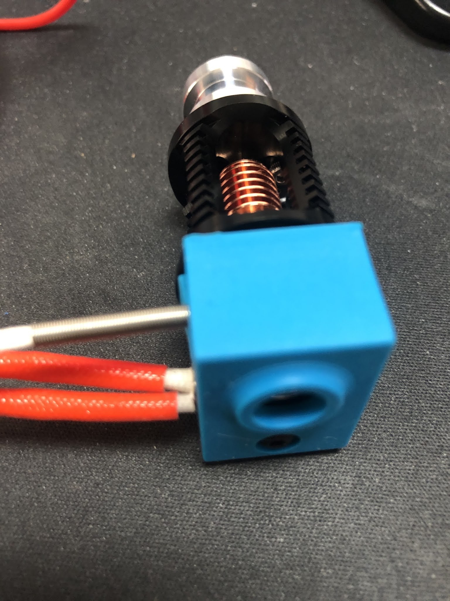
As I ordered the full kit of the BMG extruder there was a V6 clone included that I used to harvest the missing parts for Dragon hot-end. That included the 40W 24V heater cartridge as well as the right temperature sensor for the Prusa(clone).
I really liked the temperature sensor with the metal spring sleeve. Usually the cables of the temperature sensors are the ones that get damaged when people are careless when working on the hot-end.
Even though there was a silicon sock included with the Dragon hot-end. But I wanted to use the one from the V6 clone as well. There is a little problem with the fit as you can see.
But easy to fix with a sharp knife. Just cut the lip off on both sides for 2mm.
After that we have our Dragon hot-end nearly complete.
For the BMG extruder clone I strongly suggest to study the assembly manual from Bondtech® as a reference.
So I will focus on the differences here and not spent the effort for a complete guide.
Frist of all download and print this little tool from Bondtech® that helps you to cut the PTFE tube to the exact length of 6.3mm. Don't forget to create a inner chamfer with a drill bit at the end.
So know it is time to start preparing the 3D printed parts. First of all I check that the filament path is ok, by sticking some filament thru it. It is a tight fit, but that is ok. You cannot have a lot of play if you ever want to print flexible filament with it. Those parts come in their own bag and have a decent quality.
Those printed parts are from the FDM conversion of the BMG extruder by Marco Zambon (Marco Z76) that shared his files on Thingiverse. Big shoutout to Marco for his work!
Then you have to mount the threaded inserts, but be careful.
1) They are not at the same spots as the original Bondtech® BMG extruder!
2) Make sure you insert them properly with a soldering iron and don't tilt it(not like it did in this photo)!
You have to insert 3 of them, this is the first.
Here goes the 2nd.
And that is the last one.
Again, make sure the are straight in and just a smidge under the printed surface. I have heated my soldering iron up to 220°C. The prints become soft like butter at this temp and you only got one shot to get it right. If you start to wiggle around the printed part is ruined and the insert will not sit tight.
In the next step you need to insert all the square nuts and some "normal" M3 nuts. Especially this one is not reachable anymore once you have insert the hot-end. I use a longer M3 screw to push them in straight.
Now we need to prepare the plastic gear on the shaft, as we use it as tool to press fit the bearings. Put the extruder gear with the lock screw on the shaft and make sure the lock screw is on the flat side of the shaft. Do not over tighten this screw, you will need to adjust the height in a later step and this is a very small thread that is easily damaged.
Then put one of the small 5 x 8 x 2.5 mm gears on the end of the shaft.
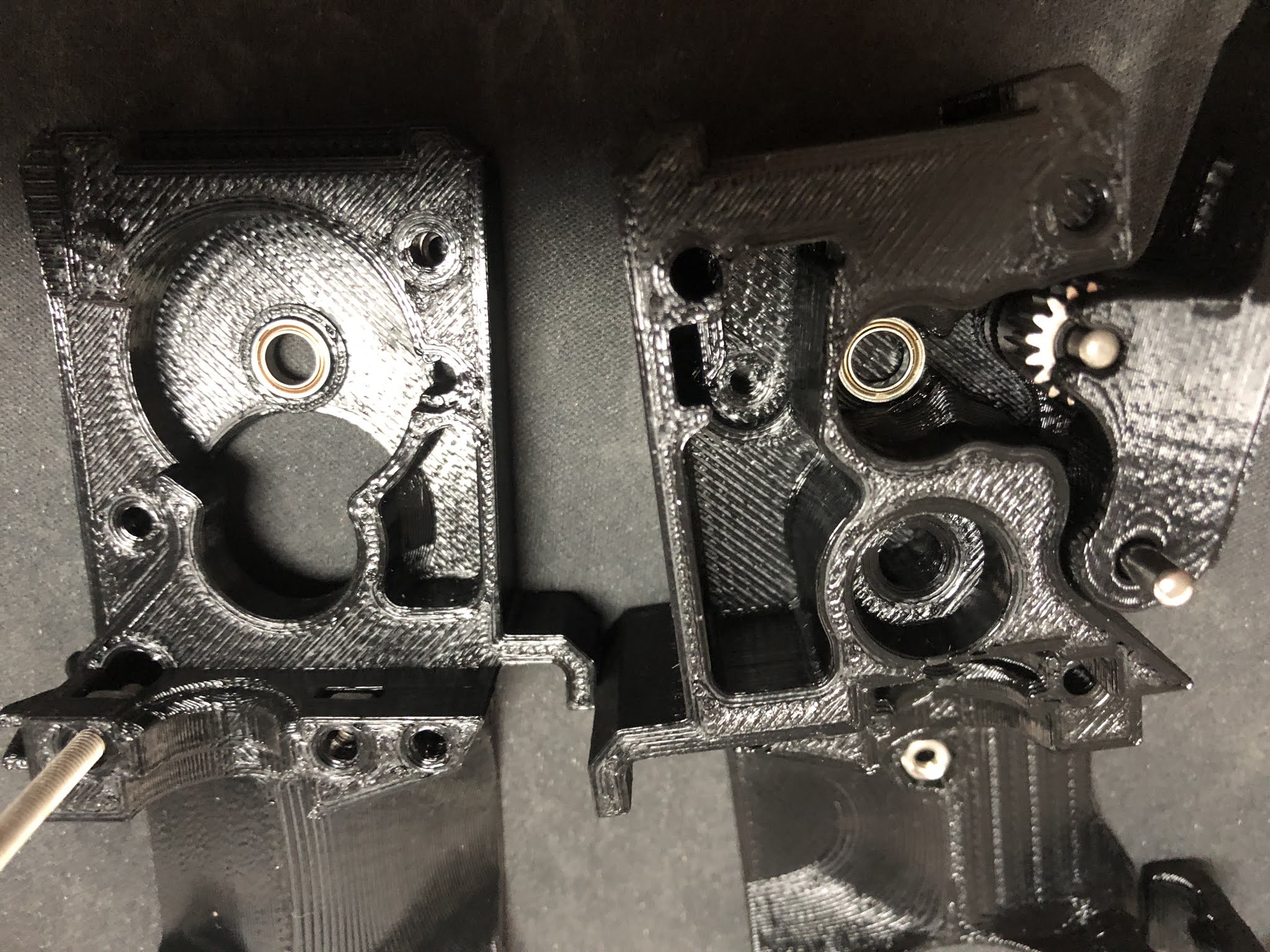
Now use this assembly to press fit the bearing into the 3D printed part. Make sure you don't tilt it as this will ruin the bearing and the seating. Then follow the same procedure for the other 3D printed part.
Next is to prepare the stepper motor. You need to adjust the height of the gear that there is around 1mm space between the gear and the stepper chassis. If that gear is mounted to high, you will grind down the plastic gear that interlocks with it. Make sure you got the orientation right and the little lock screw facing the flat side of the shaft.
Then we have to insert a M3x10 screw in this hole. It takes a bit of wiggling, but make sure to down damage anything as there will be a square nut inserted in a later step.
Next step is to mount the motor with 3 screws as shown here. The one on the left down corner is the one we inserted in the previous step. When you tighten the screw the hex wrench goes thru the hole in the 3D printed part. Again, don't mess it up! When you insert the plastic gear you can now check that the gears have proper contact with all the surface of the teeth on the plastic gear. If not, then the gear on the motor is too high.
Now it is time to insert the square nut. In my case it was not a very tight fit, so I decided to secure it with a drop of superglue. As you can see it inserted a long M3 screw to make sure there is not superglue in the threads of the nut. I also kept turning the screw to avoid the screw being glued to the nut.
I did move on to the lever next. When you open the small bag with the gears, this is how it looks like.
They put the needle bearings on the long shaft. THAT IS WRONG!
As you can see here, the long shaft is used to mount the lever in the housing, the short one is used with the needle bearings as axle for the other drive gear.
If you mix the shafts up and press fit the short one into the housing with the lever, you will not get it out anymore.
Next step is to assemble the magnets and parts for the filament sensor. Just follow the instructions from the Bondtech® or Prusa® assembly manual.
If you habe completed both side of the housing it should look like this. Make sure you have the setscrew on the shaft with the plastic gear facing to the lever(it is on the wrong side in this picture). You cannot turn the gear once the two side of the housing are together.
In my case one screw was no flush with the 3D printed part and causing problems. I ended up cutting away a little piece of plastic on the other side to make it fit.
After that it fitted perfectly and next if to use the x-carriage mount and the long M3 screws to finally hold the 2 parts of the housing together.
Next steps are outlined in details in the Bondtech® assembly manual I linked in the top of this post. Basically mount the Fans, the Pinda probe and take care of the cables. Don't forget to align the drive gear on the shaft with the plastic gear.
Once you got this done you got yourself an extruder/hot-end combo like this.
You may have noticed that there was no nozzle in the hot-end all the time. The reason is simple. I started to use the original E3D Nozzle-X in all my printers in 2019 and never had to replace a nozzle ever since. I did not have any of those nozzle at hand when I built this. But the nice thing about the Dragon design is that there is no risk of loosen up the heartbreak from the heat block when working on the nozzle. You might twist the whole hot-end in the extruder body, but you can easily twist it back in position.
I usually heat up the hot-end to 80°C and then just slightly tighten the nozzle. Especially with the copper heat blocks you can easily mess-up the heat block with too much force. Copper is a soft metal and those are small threads.
I hope that guide helped a bit if you want to build your own clone.
Last tip. If you don't have changed anything else on your clone that would require changes to the firmware, the use the firmware that Bondtech® provides for the MK3(s) and flash on the Einsy Rambo board. Besides the 3:1 ratio for the stepper motor they might have done more changes(I did not check this).
Also important! After flashing the Bondtech® version of the Firmware you have to perform a full factory reset in order to get the settings for the 3:1 ratio of the extruder stepper motor to become active. All this is outlined in their manual.