Sunday, December 10, 2023

A new project "automatic cat litter box"

 I did not post any updates for a long time. I spent some time making some money with 3D printing to recover some of the costs from this hobby. 

Unfortunately this turned out to be way more effort to comply with all laws and regulations for commercial sellers/makers. There wasn`t much to to blog about anyway. Apart from some modifications on the Voron 2.4 and a still half finished Voron 0.1, all my printers still run and run and need just little maintenance.

But I have a another problem that requires my 3D design/printing skills. We have 3 cats, one of the is quite old and has health issues. He has problems to get into a litter box with high walls and in the one we currently use, he frequently makes his business over the edge of the litter box, when he thinks he does not have enough space to full enter the box.

I also find it quite annoying to clean the litter box constantly, 3 big cats make a lot of mess. So I tried a couple of "self cleaning litter boxes". No matter if you spent just a couple hundred or over a thousand bucks, they all suck. Nearly all of them are small and all of them stop working after a while. I tried to hack a couple of them and tried my best to improve them. But after a while I just had to give up as the problems hit a point where it was unsustainable to waste more money and effort trying to fix them.

So I searched the Internet for DIY solutions for a self cleaning litter box. And I found a video from Micheal Bode https://www.youtube.com/watch?v=otlP7usU7jw , but with no further information on his project. I liked the size, yes it is big, and the ideas with the sensors. What I did not like to much was the fact he build it from wood and my fear war that the wood will soak in cat piss and smell awful soon. But in his description he linked the video that inspired him, from "haha ha" https://www.youtube.com/watch?v=xgOvI7tDEzc&t=0s . I liked it much more as he use plastic as material. But I already saw the flaw in his design. It is smaller and contains just less cat litter that then tend to stick to the walls.

But hey I am a 3D printing guy. So I searched the usual sites with STL`s for solutions. So I stumbled across a design from Thomas Krichbaumer https://cults3d.com/en/3d-model/home/self-cleaning-cat-toilett that also had a video in the description https://www.youtube.com/watch?v=wm88JU7OQdY&t=2s . His design also gave me some inspiration, but was not suitable for me as well. First our old cat would have problems to get in and would have to design something around it anyway. Second I was not sure about the size, if it is not to small either. So I decided to build my own.

My goals for the design where:

* It has to be big to give the cats enough room and hold a sufficient amount of cat litter. I settled with a drum diameter of 80cm and a depth of 50 cm. That was the perfect size for the spot where the current litter box is.

* It should be printable on a common printer like the Prusa MK3 and not require a huge printer. So the size of the parts was limited around 200mm for each side.

* There should be no need for a lot of supports as this project already used a lot of material.

* I wanted to use pins and screws to give it more stability. But also planned to glue it all together to be waterproof (or cat piss), once the design has worked out.

So I started out to design the drum first and this is what I came up with:


The drum has 13 sections. Each section has a from, a middle and a rear part. Then backplate is like a pie chart with a disc in the middle. The wall thickness is 10mm, but will some enhancements to give room for screws and surface to glue.
For the movement I have settled on a toothed bar a and gear with modul 5. The bar is not part of the middle part for a couple of reasons. First t would require a lot of support material during print. Second I can print this part much stronger, thicker walls more infill, without wasting material on the bigger parts.
I also did not include any screws to mount the bar, it will solely rely on glueing. At least for now, mybe I will have to change that.

Then I have a "sacrificial" gear that reduces the modul from 5 to 1.5 which is way more common and much cheaper. The idea here is that this part should wear out over time, can easily be replaced instead of the bar glues to the drum part.

Each drum part is around 24h of print time. I use thicker walls and a 15% infill. So there is 1 1/2 month of printing time just for the drum. That gives me enough time to source some materials and finish the design apart from the drum. 


Sunday, April 18, 2021

Prusa MK3 vs Voron 2.4

Which is the better printer?

Recently I had an argument with Chris Warkocki the admin of the Prusa community group on facebook where he casted some aspersions on the Voron printer. so he claimed that every of his customer printers would print much better and faster than the Voron and the Afterburner would have a very bad cooling.

So there is a lot to unpack here. 

First, of course you cannot have an unbiased opinion about other printers if you have such close ties to Prusa and being the admin of the fb fan group. That is human nature and we know fanboys from other areas in life. But let us have a look at the substance of his claims and make some comparisons.

Costs

A stock Prusa MK3s as DIY kit comes with a price tag of 769,-€. As Chris already mentioned that his printers are heavily modded, let's add the most common mods. 

The bear frame kit without printed parts 89,99€

One spool of PETG for the printed parts 25€

Bondtech extruder upgrade 120€

SE Mosquito hot-end 160€

Seems he replaced the EinsyRambo as well and tried SKR and Duet boards, even is experimenting with klipper that requires and additional Raspberry Pi. So that could range from 100€ to 300€ for the electronics, but to be fair we just assume 100€.

That is a total cost of 1263,99€ for the heavily modded Prusa MK3. Not take into account other mods like Mitsumi, Vesconite LM8UU bearings or real linear rails, different stepper motors, larger frame (z height) etc. 

For my Voron 2.4 I have spent roughly 1400€ including LDO steppers, robotdig linear rails, 4Gb Raspberry Pi 4, Meanwell power supplies, panels with printed Voron Loge, prepared cabling harness from fermio labs and stainless steel bolts and nuts order in large quantity(hundred more than I needed).

I have also added some parts that are not listed in the BoM to have a more safe printer that pushed the overall costs to 1500€

So the Voron 2.4 is a bit more expensive than the modded MK3, given the doubt the no other mods are made. Still they are in the same ballpark in regards to cost.

Features

The official build volume for the Prusa is 250 x 210 x 210 mm that cannot be 100% utilized from my experience. 

My Voron has an official build volume of 300x300x300 mm that can be 100% utilized as the motion system has 350mm linear rails.

The heat bed on a Prusa is basically a PCB that is relatively thin compared to the 8mm aluminium slab I have on the Voron. The thick aluminum plate is not only more stable and precise(machined surface), it is also more resistant to warping with temperature changes, the aluminum has more mass and is a very good thermal conductor. So the bed temperature is more stable and more unified across the surface area.

Another advantage is that the Prusa PCB head bed is powered by 150W(24V6.25A), while the Keenovo heat mat on my Voron is has 400W (230V). It heats up quicker and does not stress the power supply or board electronics.

The Prusa motion system is still based on 8mm steel roods, 2 per axis. The Voron comes with linear rails, 4 for Z, 2 for Y and 2 for X. 

Also part of the motion system are the 5 1.8° stepper motors on the Prusa(2 for Z, 1 for X,Y,E each) while the Voron has 7 Steppers in total, 4 1,8° for Z that are reduced by pulls in a ratio of 20 to 80 teeth, 2 0.9° for Y and X movements and 1 for the extruder.

In numbers that means the Tr8x8 lead screw on the MK3 with the 1.8° stepper motors allow a resolution of 0.04 mm layer height. With the Voron also with 1.8° steppers and a GT2 fully with 16 teeth, but a ratio of 1:4 gets to the same layer height of 0.04 mm. But on the X and Y the 0.9° steppers on the Voron allow for more resolution that the Prusa.

Both design use printed parts, The Prusa comes with PETG parts, ABS is used for the Voron as PETG fails in a heated chamber.

I will not rub on the EinsyRambo board on the Prusa vs my 2 SKR V1.4 turbo boards as we included 100€ for a board upgrade in the Prusa in the cost calculation above. But I guess it is obvious that the combination of 2 SKR boards with Klipper doing the heavy lifting on a Raspberry Pi outperforms the old Prusa 8bit board.

Both can use steel sheets as build pate with PEI stickers or powder coating texture that are held in place by magnets. The Prusa has some needy magnets as inlays in the heat bed PCB( that like to fall off over time). The Voron uses a magnetic sticker on top of the aluminium bed. Both are rated up to 120°C before the magnetic force degrades.

Both printers have a inductive probe for bed leveling by default that require a steel sheet. But in addition the Voron has a probe for the nozzle. That means if you swap the nozzle or the hot-end(which is very easy on the Voron) then the nozzle probe can measure the new distance of the nozzle relative to the print bed and you don't need to adjust manually every time like on the Prusa(first layer calibration).

Per design the Voron has an enclosure. That helps with materials like ABS that tend to warp, but also keeps the fumes inside. The Voron even has a simple air filtering system. 

The Prusa uses 3 pin fans that allow the firmware to detect if a fan is not spinning which could lead to overheat in case of the hot-end fan. The Voron uses only 2 pin fans by default.

In terms of security features the Prusa has some self check abilities. The Voron has a thermal fuse for the heat bed by default that kills the power to the heat mat at 120°C. 

I have added a filtered C14 power inlet in my Voron that has 2 fuses. In addition I also added a 6A circuit breaker with built-in ground fault circuit interrupter. But that is not part of the standard Voron BoM.

Print Speed

I have to admit that I did no do my own tests yet as my Voron 2.4 is not finished yet. So I can only rely on information that other Voron users share. I guess a full video of a print with a clock running is a trustworthy source. 

Problem is that there was no real "standard" print. The often used bench boat does not say anything about size, infill percentage, material etc. The range of benchy times on a Voron 2.4 range from under 10 to 14min. I have seen videos from MK3 around 15min for a benchy, but again it is hard to compare as there is no standard for the benchy.

The actual speed you put into your slicer is a desired value. Just because you put in 800mm/s it does not mean your printer can do 800mm/s. Same goes for adjustments on the printer itself. 

So there are some videos from MirageC where he claims to print with 800mm/s with his HevORT CoreXY. Vez3D has a very fast coeXY, so does Anney_Engineering.

There is even a speed benchy contest on the Annex-Engineering discord channel. They have rules for the settings that lead to more comparable results.

One Voron 2.4 from joshmurrah (standard with afterburner) with 11:15min for the benchy and one Mk3 heavily modded with bear frame, linear rails, different hot-end/extruder and running klipper with 12:43min from Techromancer that looks a bit like cheating as he uses only one corner of the bed and thereby uses the advantage that the gantry if stiffer at the end as in the middle. And his MK3 is running klipper as well.

What I have not seen is a real fast benchy from Mr Warcocki. Not even a full video of his fast prints. Sometimes he shared short video sequences on FB and claimed a speed that cold not be verified in any way. 

To understand why the bed slingers like a Prusa Mk3 can hardly beat any CoreXY is very simple. There are physical limits. While the CoreXY design has the power of two stepper motors pulling at any X or Y movement, the MK3 design has a single stepper that must move the whole print bed plus the print itself(more mass).

Having that said the current best time is a delta printer.


Conclusion

To me the Voron 2.4 stock printer outperforms the Prusa MK3, even when the MK3 is heavily modded in many areas. You simply get a bigger, faster printer that already come with an enclosure.

When you want to opt for speed you can add a high flow hot-end from the beginning and don't have to throw money for a standard hot-end out of the window.

Changing the hot-end on the Voron works like a charm and is so easy. Compared to the mess on the MK3 where you have to completely disassemble the x-carriage and cabling to the board.

Why someone would spent >750€ on a printer kit, just to throw away most parts while replacing them and spend more money instead of directly building the printer of desire is a mystery to me.

I guess you have to be a real fanboy.


The end of the Dragon Hotend?

Is this the end? Let's try to unravel the mystery.


What is the Dragon hot-end?

The Dragon hot-end is a hot-end that was originally introduced by the Chinese company Phaetus. It combines elements from the E3D V6 with elements of the Mosquito by Slice Engendering. They have copied the design of the heartbreak and the way that the heat block is mounted to the heat sink. The E3D V6 uses the heat-break also as the mechanical mount between the heat block and heat sink. Unlike the V6 design the Mosquito uses small stainless steel pipes with small screws to heat block tot he heat sink, that allows to have a very thin metal tube with cooling fins as heat break. This part was obviously copied by the Dragon hot-end.

Mosquito by Slice Engineering

On the other side the Dragon kept the exact out dimensions of the E3D V6, including the mount ring which is optional on the Dragon(at least the TL versions I have). So in contrast to the Mosquito with its very distinct shapes that usually requires a different mount and even a different Extruder body (on the Prusa Mk3 for example), the Dragon is a drop-in hot-end that does not require any changes.

clone of the E3D V6

Not only the mount, also the heat block and the mounting for the heater cartridge and the thermistor are the same on the Dragon and the E3D V6.

Triangle Labs Dragon without mount ring

Slice Engineering has a number of patents on their products that can be found here, some are still pending.  https://www.sliceengineering.com/pages/ip

Now it seems like Triangle Labs fears that SE could sue them for patent infringement and being forced to pay royalties. This is why they have now stopped selling the Dragon hot-end.


If Phaetus will also stop selling the Dragon hot-end is not clear yet. But definitely bad news for all users of the TL Dragon as they might not get any spare parts in the future. 
According to Mr. Warkocki, the admin of the Prusa community group on facebook, SE has denied that they actually threatened Triangle Labs. But that does not mean that could go down that road in the future and Tl just proactively stopped selling it to avoid problems in the future.

Other sellers hoped up on AliExpress now, selling Dragon hot-ends for less than $20. If they are even close tot he quality of the TL Dragon hot-end, I don't know.

If there is enough substance for an infringement claim would be up to a court to rule on. Or if the SE design is that ground breaking different from the V6 that is justifies being protected by a patent could also be subject for discussion.

To me the fact that 3D printing was already invented in the early 1980s(FDM 1989), then protected by patents until the early 2000s held by companies like Stratasys until it became available for hobbyist because of the reprap project in 2008, is a point against patents. Especially as it seems we are now going back from open/free technology, back into the world of patents and closed development.

I guess Prusa is a good example that you can have development and make money while you open source your products, if you have a good product for a reasonable price and offer a good service.


Thursday, April 1, 2021

Mosaic Palette 2S Pro or 3 Pro?

Two weeks ago I finally ordered my Palette 2 Pro. I hate the Prusa MMU2 as it is so unreliable und far from being easy to use. So I was thinking to get a Palette for a while.

But I have so many other projects going on that 750€ was quite a sum for me right now. But while waiting for my Voron 2.4 parts I decided to get one, finally.


But this week Mosaic announced the Palette 3 Pro, for the same price as the 2S Pro and in addition you get a $100 off for pre-orders. So seems that was just bad timing.

But what really annoyed my was that there is no upgrade this time as the internals have changed so much. I would appreciate if they would give a bigger discount for existing customers.

I have not yet decided if the Palette will go on one of my MK3 clones or even on the new Voron. I guess the Palette would slow down the Voron.

I also got most of the mechanical parts for my Voron 2.4. The SKR boards are still missing, according to tracking they are in Germany since begin of March. The heat mat is still not available. I started to put the frame and rails together today and already ran out of M3x8mm screws. So I guess having the build mostly done over Easter will not happen.


Sunday, March 21, 2021

Is EVERBODY building a Voron now?

It seems like a huge community is building a Voron now. It is really hard to get the parts.

I had ordered some parts from Fermio Labs, like the print bed, the LDI stepper motor for the Afterburner hope-end and the IGUS® cable chains.

Then a few days later some more parts where available and I ordered them. Unfortunately I did not pick the frame kit in black from LDO, that was then sold out in 2 days. But I got the LDO stepper motors for X any Y axis (0.9°) and picked the wire harness.

I have could make it by myself. But if you do the math. The complete harness costs me 114,90€. If I buy a 100 meter roll of the Helukabel Heluflon®-fep-6 in 0.25 mm² it cost me around 50€. The sourcing guide says you need 250 feet (or around 77 meters). Then I need the 0.5 mm² also, plus the JST and Molex connectors (just few cents) and the work I have to spent. They advertise that the connectors are properly labeled. If you don't have the tools(I got them) you would also need to spent a fair amount of money on proper tools for the Molex and JST connectors.

Well, I will report about the quality once I receive the harness. But that seem to be a fair deal to me.

The motors for the Z axis was nowhere to find, but then I stumbled across the hobby-store.pl . The had the LDO motors and I also ordered the steel shafts as they were cheap. I am not sure if I will use them as I also have a 5mm stainless steel rod here that I wanted to use. But cutting and grinding stainless steel is a pain.

I got the screws for my Voron as well. I try to use stainless steel bolts and nuts when possible and usually order them in larger quantities by 100, 500 or even 1000. So I spent round about 100€ for the bolts and nuts.

Some small parts arrived from Chine as well. The self tapping M2 x10, the JST connector set, the magnets and the Z inductive probe sensor.

I got the Mean Well power supplies both from Amazon for a good price.

I ordered the spring steel sheets from Energetic3D store. I am happy with the ones he provided for my Prusa clones and the Elegoo Mars 2 Pro printers.

So for know I can only wait for the resining parts like the frame, the heat mat and some others to become available again. 

Then I still wait for more parts to arrive from China, like the Bigtreetech SKS V1.4 turbo boards, the fans, the nuts for the extrusion profiles and the bearings. 

There are some electrical parts missing as well. But I plan to use proper circuit breakers and ground fault circuit interrupter for this printer. I am also thinking about some LED lights and some gadgets.

One would be a nozzle camera. 


Sunday, March 14, 2021

First Voron parts are coming in, best tools for threaded inserts

 So I have started to print the Voron parts from eSUN ABS+. After a little bit of fiddling I got the ABS+ to print fine on my Prusa clones.


I have also started to melt in the threaded inserts. Therefore I bought a cheap soldering iron for 8,99€ only on Amazon.


I doubt it is any good for any soldering applications, but the tip design and the low energy made it the right tool for my purpose.


So bought this set of special tips for threaded inserts on Amazon for 9,99€ that perfectly fit to this soldering iron.

With the soldering iron set to the lowest power (200°C) it is just enough to gently melt in the threaded inserts into the print. You don´t want this to be too hot, as then the plastic will melt like butter and it will be hard to get a good and strong bond between the insert and the plastic part.

The other parts that came in where the linear rails I ended up ordering directly from robotdigg.com. Ordering was easy and shipping including tax was cheap.


I am still struggling to the get stepper motors from LDO that I want. But I did order the build plate in 300x300x8mm, the IGUS® cable chains, the extruder stepper motor. So that I can at least build the Afterburner extruder.
The frame is also a problem. I cannot get it from a local shop like Fermio Labs as it is always sold out like the stepper motors. If I could figure out if the LDO frame kit is similar in the dimensions as the Mitsumi kit, I would have ordered this one. But the problem with cheap rails is often that the surface for the linear rails is much smaller as the linear rails touches the extrusion profile just on the edges of the linear rails.


Tuesday, March 9, 2021

Voron is coming !

 I have quite a range of Prusa MK3(s) clones now. I did not bother to build a Prusa Mini yet, as I don't have a use case for it. An advantage would be the smaller plate, as a lot of parts I print would fit and I would not have to wast so much energy to heat up a large bed. But on the other hand the design does not look sturdy to me and I don't like bowden extruders.  Honestly I still have 3 Ender 2 from Creality, that are very similar.

As many other I was waiting for a Prusa Core XY design, but I have lost hope on that. I guess it would be at least 2000€ if it every comes.

So I looked around for a nice Core XY design over the last months and found that the Voron Design has a lot of support. From CAD files to parts lists and even a sourcing guide. You can decide on the build volume, I choose to go with 300mm on all axis. What I really like is the approach to go with reasonably parts. They don't always recommend the most expensive option. They have a lot of parts from Aliexpress.

For example on the linear rails. For sure Hiwin makes good quality, if you manage to get original ones. But they recommend to buy from Robodigg. why? Because it is a 3D printer, not a CNC milling machine. I have seen a lot of Prusa modded MK3 with Hiwin rails and I always ask myself WHY? Why would you spend so much money for those expensive part if the rest of the printer cannot keep up with it?

Then of course there is the question why people buy Prusa printers in the first place if they anyway are going to replace the frame(Bear Mod), the linear rails, the hot-end etc. Why not simply get the parts and build a clone from the start like I did now many times?


Ok, but back to the Voron. I was looking for a printer that can print fast, but with high quality. Some of the videos I have seen on the Voron where quite impressive. I also looked into the HevORT, but that seemed to me like a lot of wasted money. Maybe good for someone who needs a huge build volume.

So my estimated budget for the Voron 2.4 is 1200€, this is what I have spent so far.

For Pulleys, idlers in anodized black and some timing belts I spent around 110€

For 6mm & 9mm GT2 belts and BMG Extruder parts from Triangle Labs I spent 80€

24V Fans for Hotend and Printcooling 15€

Washers, screws and magnets about 30€

Robodigg black Linear Rails  120€ 

MeanWell 5v and 24V Power Supplies 52€

2x BIGTREETECH SKR V1.4 Turbo 32Bit  86,79€

LP08 inductive sensor 5,82€

MINI12864 v 1,2 LCD Display 9,63€

I have problem to source some parts like the stepper motors. I want some quality from LDO, not the usual crap you get on aliexpress.

If you wonder about the quality of the printed parts. This is eSUN ABS+ printed on an original Prusa MK3 in an IKEA enclosure. There was no profile for ABS+ and all profiles for ABS did not work, but I got only ugly warped parts So I had to come up with something on my own to get started.


But in the end I got it running. I used the ABS profile as a base. Then I changed those values and got some good result

print fan to 15% min and 30% max, on all time and 

nozzle temp 240°C first Layer all other 235°C

bed temp 100°C first layer 95°C for all other layers

I change the extrusion with to 0.5 for the first layer. 

Sunday, February 21, 2021

How to export multiple Mesh bodies as one STl with Fusion 360

 I stumbled across a problem with Fusion 360. I wanted to combine 2 parts into one, but I only had the STL files, not the step file. But you might also find this very handy if you just want to combine different STL files into one. They not even have to be connected to each other.

This is the hot-end mount from the Voron printer that is usually 2 parts. For some reason the version for the Triangle Labs Dragon Hotend was not in the CAD files the project provides and only available as STL.

Fusion 360 let you import STL files as mesh bodies, but you cannot export them together as one. That is only possible for solid bodies.

The problem was that those mesh objects have too many faces to be converted into solid bodies. There is a limit of around 20000 faces for the mesh to BRep conversion.

There is the option to reduce faces, but that also means you lose some details. So here is another way to do it.

So I started to import the 2 STL files in a new design in Fusion 360.


Then I had to align the mesh bodies exactly, so that all axis would fit, but not overlap.


I saved my work and waited to sync with the Autodesk cloud. The go to the autodesk cloud with a web browser -> https://myhub.autodesk360.com/ 

Navigate to the folder where you saved your project, then at the end of the filename there is a download icon. Navigate to the format you want. 


Then you get a message that the project is being converted for you.


Once your project has been converted you get an email with a download link.


So not only you got your STL files back as one, Autodesk did the conversion on their servers for you.

Now the 2 part become one and were ready to print.


Saturday, January 30, 2021

Printer Calibration

 Many people share their print settings online. Some are really good, like the ones from Chris Warkocki aka codiac2600 who publishes them in the Prusa Facebook group and on GitHub.

While for many those profiles work very well out of the box, to me there is always some room for improvements that lead me to have my own profiles per printer, not per type of printer.

There are no 2 identical MK3S in the world. From little variations in the used parts over the care that was put in to put it together to the variation of adjustments like the belt tension there is always a difference in 2 printers.

So for really good prints, you need to spent some effort to calibrate your printer. Also if you have multiple printers like myself, then you want the printed parts to come out the same quality and size on every printer.

In the beginning I spent hours to adjust model dimensions in CAD between my first two printer.

But before we start, just a reminder that this is very much depending on the material you print and the shrinkage is dependent on the material and might have huge effect on the size of an object. 

So one of the first things I start with is the extruder stepper. You can use Octoprint and the Terminal to send commands and receive the output.

With "M503" you get the current settings. Not just the steps per unit, but this is the part that is in focus here so I cut the rest out. I also assume that you have already some filament preferable PLA loaded.

Send: M503

Recv: echo:Steps per unit:

Recv: echo:  M92 X100.00 Y100.00 Z400.00 E415.00

As I have a BMG extruder clone installed I have 415 steps for the extruder motor per unit.With a standard extruder you might have less, roughly 1/3. 

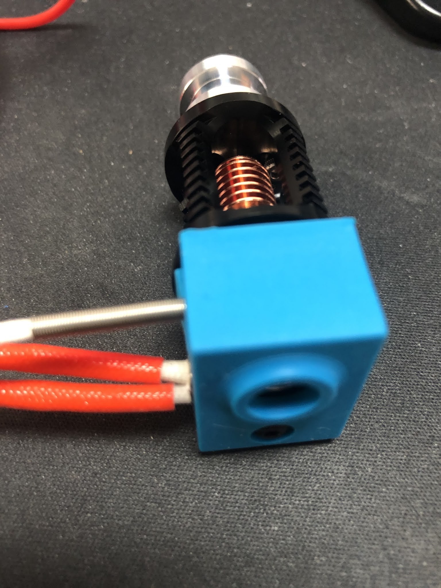
Now we need to make accurate measurements or we will only make things worse. Take some calipers or a very precise ruler. A folding ruler like shown in some videos is not an appropriate tool for this job. The maximum my calipers can measure is 150mm. Now measure the 150mm from the top of the extruder body and mark the filament with a fine permanent marker.

Next we heat up the nozzle and maybe just give a 5°C more than usual to make sure the filament is properly molten in time. With the nozzle at temperature we go back to the terminal in Octoprint. And set the count for the extruder stepper to 0.

Send: G92 E0

Recv: ok

Again, make sure the nozzle is at temperature. Then send the command to extrude 100mm of filament. 100mm is just fine as it leaves you with plenty length to measure. If you would extrude 150mm the mark maybe already in the extruder body and not visible and/or reachable to measure.

Send: G1 E100 F30

Recv: ok

Then measure the distance from the extruder body to the mark you made with the permanent marker. In my case I there was 47mm of filament left. So the extruder extruded 103mm instead of 100mm.

We need a little bit of math now to calculate the new values based on the ratio. 

100/103 x 415 = 402.91

That is quite some difference. For the next stepp we need to terminal again to send the new value to the printer.

Send: M92 E402.91

Recv: ok

But we also need to save it to the eeprom.

Send: M500

Recv: echo:Settings Stored

We can now read it back from the eeprom and ask for the values.

Send: M501

Recv: echo:Hardcoded Default Settings Loaded

Send: M503

Recv: echo:Steps per unit:

Recv: echo:  M92 X100.00 Y100.00 Z400.00 E402.91

As next step I usually perform a first layer calibration. There are plenty of instructions about it that you can find with google or at the Prusa blog or forum. Important is that the surface is clean, so you don't have adhesion problems.

Then I print a 1 layer test rectangle of 40x40mm and let it cool down. Then I measure the thickness with my calipers. AS I use the cheaper powder coated steel sheets from China, they have a rougher surface as  the Original ones from Prusa. Because of the texture you will not be able to get a 0.2mm thickness with a 0.2mm layer height. Usually I end up with a thickness between 0.2 and 0.3 mm. 0.25 is what I try to archive. 

But be careful to not scratch the build surface with the tip of the nozzle. And keep in mind to you have to do this for every sheet. This is why Prusa added the feature to store values for multiple sheets.

When I am happy with my first layer, then I move onto the other dimensions. Usually I print a cube of 40x40x40mm. I often see people using cube with just 20mm edge length. That save some material, but as short the distance is as smaller the deviation will be that you can measure. The optimal size would be 200x200x200mm I guess, but that costs a lot of material as you might need to redo this step a few times.

Once the print is cooled down we start to measure. Make sure you mark the surface somehow so you know later which axis it is. There are cubes with marks, but they introduce irritation in the surface that might lead to false measurements.

So again in my example those where my measurements:

X 39,80mm  Y39,60mm  Z 40,70mm

Similar math as we did for the extruder needs to be done per axis now.

X = 40 / 39.8 x 100 = 100.50

Y = 40 / 39.6 x 100 = 101.01

Z = 40 / 40.7 x 400 = 393.12

So we have our new values now and need to program them into the eeprom of the printer.

Send: M92 X100.50 Y101.01 Z393.12

Recv: ok

Save them

Send: M500

Recv: echo:Settings Stored

Read back and check values

Send: M501

Recv: echo:Hardcoded Default Settings Loaded

Send: M503

Recv: echo:Steps per unit:

Recv: echo:  M92 X100.50 Y101.01 Z393.12 E402.91

So now all stepper motors are calibrated for now. You might want to revisit this calibration once in a while to check if everything is till ok with you favorite print profile. As you can see here I still have a little "elephant foot" on the bottom of my test cube. There is are also some vertical lines that you can barely see. 


I have noticed that the nozzle was scratching over the print while printing and making a squeaky noise sometimes. Could the steps for the z axis be wrong? Well, as the end result was exactly the 40mm the 0.2mm layer height seemed to be ok. Did it?

No, remember when I said above that you will never get an exact first layer height of 0.2mm with a textured print bed?  So if your measured first layer height is 0.25mm, then the cube height should be 40.05mm, not exactly 40mm as you have to add the difference from the first layer.

So I had to adjust the steps for the z-axis again. 

Last, but not least there is shrinking. Shrining is what makes objects warp on the drin surface. When the molten plastic cools down it shrinks a bit. Some plastics shrink a lot, like ABS, some less like PLA. so you might have a PLA cube that is exactly 40mm on all sides, but the same cube printed in PETG it is not.

Then I focused on the surface. So I just printed a rectangle with 10mm height. What you see in the photo is the pain top surface, no ironing. You can nearly see some marks from the infill.


But still I was not happy with the top surface. So the next area to improve the settings was the print profile in Prusa slicer. In the filament settings you find the extrusion multiplier. I used the pretty PLA profile from Chris as a base that had it set to 0.95 (95%). I ended up using 0.93(93%) in this case.


Keep in mind that this might also vary on the filament you use. Especially when you use cheap filament that varies in diameter over the length of a spool, the results might not be very good. 

You can also set the change the flow multiplier in firmware  with M221. But I prefer to do this in the slicer profile as this is very much different depending on the filament. 

Basically the math is Total flow rate = Flow multiplier in firmware (M221) x Extrusion multiplier in PrusaSlicer. So a flow multiplier in the printer of 1.05 and a multiplier of 0.95 in Prusa Sliver would be a total flow rate of 0.99 again.

Once you have dialed in your slicer profile, you might want to revisit the calibration again as those settings might affect the overall values of the size of the printed part. If you really need that precision.


Wednesday, January 27, 2021

Triangle Labs Dragon hot-end and BMG extruder clone assembly

 So in the last post I showed off what I bought during 11.11. sale on aliexpress and after.

This time let get into building the Triangle labs Daron hot-end and their BMG extruder clone.

The Dragon hot-end comes in this plastic case with the parts, some spare parts and some hex wrenches. Keep in mind that you only get the hot-end, but no heater cartridge or temperature sensor.

BTW: This is the high flow (vulacno like) version. I have the normal version running in another Prusa MK3S clone for a couple of weeks now.


As I ordered the full kit of the BMG extruder there was a V6 clone included that I used to harvest the missing parts for Dragon hot-end. That included the 40W 24V heater cartridge as well as the right temperature sensor for the Prusa(clone).


I really liked the temperature sensor with the metal spring sleeve. Usually the cables of the temperature sensors are the ones that get damaged when people are careless when working on the hot-end.


Even though there was a silicon sock included with the Dragon hot-end. But I wanted to use the one from the V6 clone as well. There is a little problem with the fit as you can see.


But easy to fix with a sharp knife. Just cut the lip off on both sides for 2mm.


After that we have our Dragon hot-end nearly complete.


For the BMG extruder clone I strongly suggest to study the assembly manual from Bondtech® as a reference. 

So I will focus on the differences here and not spent the effort for a complete guide.

Frist of all download and print this little tool from Bondtech® that helps you to cut the PTFE tube to the exact length of 6.3mm. Don't forget to create a inner chamfer with a drill bit at the end.


So know it is time to start preparing the 3D printed parts. First of all I check that the filament path is ok, by sticking some filament thru it. It is a tight fit, but that is ok. You cannot have a lot of play if you ever want to print flexible filament with it. Those parts come in their own bag and have a decent quality.

Those printed parts are from the FDM conversion of the BMG extruder by Marco Zambon (Marco Z76) that shared his files on Thingiverse. Big shoutout to Marco for his work!


Then you have to mount the threaded inserts, but be careful. 

1) They are not at the same spots as the original Bondtech® BMG extruder!

2) Make sure you insert them properly with a soldering iron and don't tilt it(not like it did in this photo)!


You have to insert 3 of them, this is the first.


Here goes the 2nd.


And that is the last one.


Again, make sure the are straight in and just a smidge under the printed surface. I have heated my soldering iron up to 220°C. The prints become soft like butter at this temp and you only got one shot to get it right. If you start to wiggle around the printed part is ruined and the insert will not sit tight.

In the next step you need to insert all the square nuts and some "normal" M3 nuts. Especially this one is not reachable anymore once you have insert the hot-end. I use a longer M3 screw to push them in straight. 


Now we need to prepare the plastic gear on the shaft, as we use it as tool to press fit the bearings. Put the extruder gear with the lock screw on the shaft and make sure the lock screw is on the flat side of the shaft. Do not over tighten this screw, you will need to adjust the height in a later step and this is a very small thread that is easily damaged.


Then put one of the small 5 x 8 x 2.5 mm gears on the end of the shaft.


Now use this assembly to press fit the bearing into the 3D printed part. Make sure you don't tilt it as this will ruin the bearing and the seating. Then follow the same procedure for the other 3D printed part.


Next is to prepare the stepper motor. You need to adjust the height of the gear that there is around 1mm space between the gear and the stepper chassis. If that gear is mounted to high, you will grind down the plastic gear that interlocks with it. Make sure you got the orientation right and the little lock screw facing the flat side of the shaft.
 

Then we have to insert a M3x10 screw in this hole. It takes a bit of wiggling, but make sure to down damage anything as there will be a square nut inserted in a later step.


Next step is to mount the motor with 3 screws as shown here. The one on the left down corner is the one we inserted in the previous step. When you tighten the screw the hex wrench goes thru the hole in the 3D printed part. Again, don't mess it up! When you insert the plastic gear you can now check that the gears have proper contact with all the surface of the teeth on the plastic gear. If not, then the gear on the motor is too high.


Now it is time to insert the square nut. In my case it was not a very tight fit, so I decided to secure it with a drop of superglue. As you can see it inserted a long M3 screw to make sure there is not superglue in the threads of the nut. I also kept turning the screw to avoid the screw being glued to the nut.


I did move on to the lever next. When you open the small bag with the gears, this is how it looks like.
They put the needle bearings on the long shaft. THAT IS WRONG!


As you can see here, the long shaft is used to mount the lever in the housing, the short one is used with the needle bearings as axle for the other drive gear.


If you mix the shafts up and press fit the short one into the housing with the lever, you will not get it out anymore.

Next step is to assemble the magnets and parts for the filament sensor. Just follow the instructions from the Bondtech® or Prusa® assembly manual. 

If you habe completed both side of the housing it should look like this. Make sure you have the setscrew on the shaft with the plastic gear facing to the lever(it is on the wrong side in this picture). You cannot turn the gear once the two side of the housing are together.


In my case one screw was no flush with the 3D printed part and causing problems. I ended up cutting away a little piece of plastic on the other side to make it fit.


After that it fitted perfectly and next if to use the x-carriage mount and the long M3 screws to finally hold the 2 parts of the housing together.

Next steps are outlined in details in the Bondtech® assembly manual I linked in the top of this post. Basically mount the Fans, the Pinda probe and take care of the cables. Don't forget to align the drive gear on the shaft with the plastic gear.

Once you got this done you got yourself an extruder/hot-end combo like this.


You may have noticed that there was no nozzle in the hot-end all the time. The reason is simple. I started to use the original E3D Nozzle-X in all my printers in 2019 and never had to replace a nozzle ever since. I did not have any of those nozzle at hand when I built this. But the nice thing about the Dragon design is that there is no risk of loosen up the heartbreak from the heat block when working on the nozzle. You might twist the whole hot-end in the extruder body, but you can easily twist it back in position.

I usually heat up the hot-end to 80°C and then just slightly tighten the nozzle. Especially with the copper heat blocks you can easily mess-up the heat block with too much force. Copper is a soft metal and those are small threads.

I hope that guide helped a bit if you want to build your own clone.

Last tip. If you don't have changed anything else on your clone that would require changes to the firmware, the use the firmware that Bondtech® provides for the MK3(s) and flash on the Einsy Rambo board. Besides the 3:1 ratio for the stepper motor they might have done more changes(I did not check this).
Also important! After flashing the Bondtech® version of the Firmware you have to perform a full factory reset in order to get the settings for the 3:1 ratio of the extruder stepper motor to become active. All this is outlined in their manual.


A new project "automatic cat litter box"

 I did not post any updates for a long time. I spent some time making some money with 3D printing to recover some of the costs from this hob...