First I wanted to design and build my own controller, but then I found this one on ebay.
DC 12v 24V 48V 2-Way 4-Wire PWM Temperature Control 7,85€
I cannot beat the price and so I ordered it. It came with 2 temp sensors. You can attach 2 sensors, 2 fans and a buzzer for an alarm that you can configure.

But now I need a case for this, one that I could simply screw unter the Ikea Lack table, so that I can see the digital temperature display. Well, I have a 3D printer and Fusion 360!
So I designed a simple case that could be mounted in a 90° angle under the table.


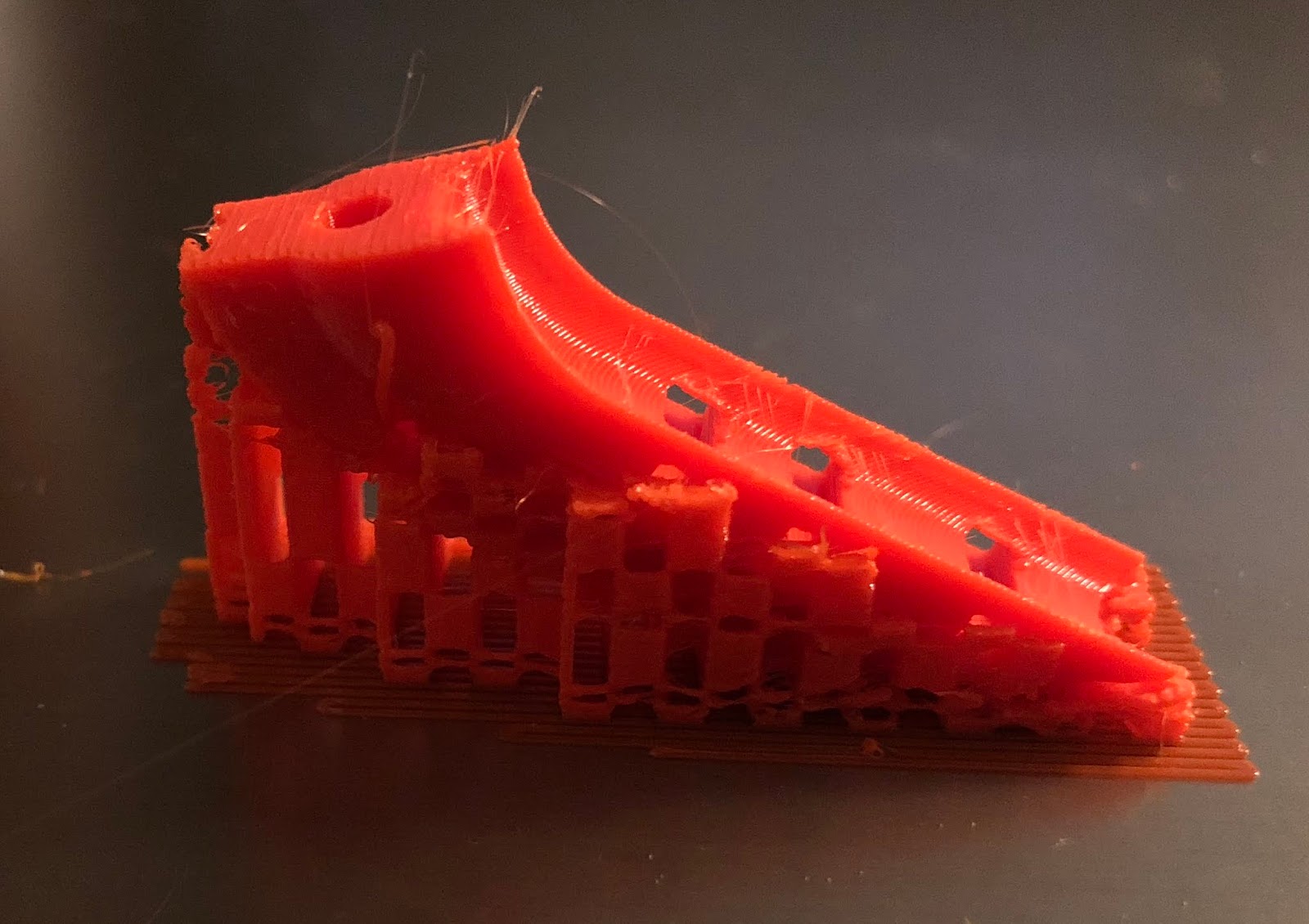
Then I printed it. Does not look nice, but I was in a rush. Also I have problems with the black PETG Spool from Prusa. Not sure what the problem is, blue, white and Prusa orange prints fine.

When screwed the circuit board on it with M3x6mm screws, I need to be careful not to bend the circuit board and break it. Usually I would have added some stand offs, but then it wold be more difficult to print.

The cover fitted perfectly, even the holes for the fan and sensor connection had the perfect location and size. Measure twice, print once!

The other element is the radiator with the fan. I need to print a mount for the radiator as well. Again I designed one in Fusion 360.

Printed it looked like this with the radiator on. As you can see, the idea is to clamp the mount between the radiator and the fan. The radiator has 4 holes with M3 threads and the screws are supposed to go thru the fan and the mount in the radiator.

And this came directly from Austria, the Noctua 120mm NF-F12 PWM fan. I explained already in the earlier post that why I decided to use this fan. It has more static pressure and is designed for the usage with radiators.


The way I mounted the fan to the radiator the air will be sucked thru the radiator. I am not sure if it would be better to push the air thru the radiator. In that case I need to flip the fan around.

I also tested the water pump meanwhile. It is a PWM controlled pump and has a 4 pin connector like a PWM fan. So in theory, if there is not PWN signal the fan/pump should run on full speed. This is why you can connect a 3 pin computer fan to a 4 pin connector on the motherboard and it will work, just without speed control.
The pulse-width modulation (PWM) control signal is a square wave operating at 25 kHz, with the duty cycle determining the fan speed.
The pump is supposed to run always at full speed. If I would PWM control the pump, then the hot water might get stuck in the hot end while I measure the water temperature somewhere in the return flow. But without the pump running the temp would rise in the hot end, but not the return flow.
But the fan for the radiator can be RPM controlled, based on the temperature of the water in the return flow.
And as a side note. The sense/tacho signal from the pump will be connected to the signal input from the Einsy board that usually monitors the speed of the hot end fan. If the pump fails, the printer will shut down the heaters. Just like the original design with the air cooled hot end.
I was basically read to put everything together, but then the PFTE hose came with hard knicks that makes them unusable. This is not the regular 2/4mm PTFE tube that is used for the 1,75 filament in 3D printing. This one is 3/4mm. I was hoping to gain more flow by the bigger inner diameter.
But this made me think twice if the material and wall thickness of the hose is the right choice.

So I ordered a 2/4mm Nylon hose. Honestly this look like regular PVC hose that you normally use in fish tanks. I did find some PVC hose with a Nylon mesh for reinforcement, that is used for compressed air, but not in 4mm. The picture from the seller on ebay shows Nylon printed on the hose, but signs of a mesh.

Then I thought about how to attach the hose to the printer. My idea is that both hose go upwards from the hot end, over the frame and down in the back. As my power supply with be mounted under the Ikea Lack table anyway, I need the bracket to enforce the frame. So I designed one that could clamp the hose and bend them backwards without hard knicks.


And mounted to the printer like this, instead of the power supply.

With Meshmixer I found the best way to print my new cable holder design. My design leads the cables in a 45° upwards instead of straight back to the printer. Why? Because if you printer several objects in series, there is a lower risk you hit something with the cables.


No comments:
Post a Comment