Thursday, December 13, 2018

The MK52 heat bed and the Rambo Einsy case

While I was busy with the assembly of the X, Y and Z axis. I printed some stuff.

Again I followed the instruction on the Prusa website:

Prusa Heatbed assembly

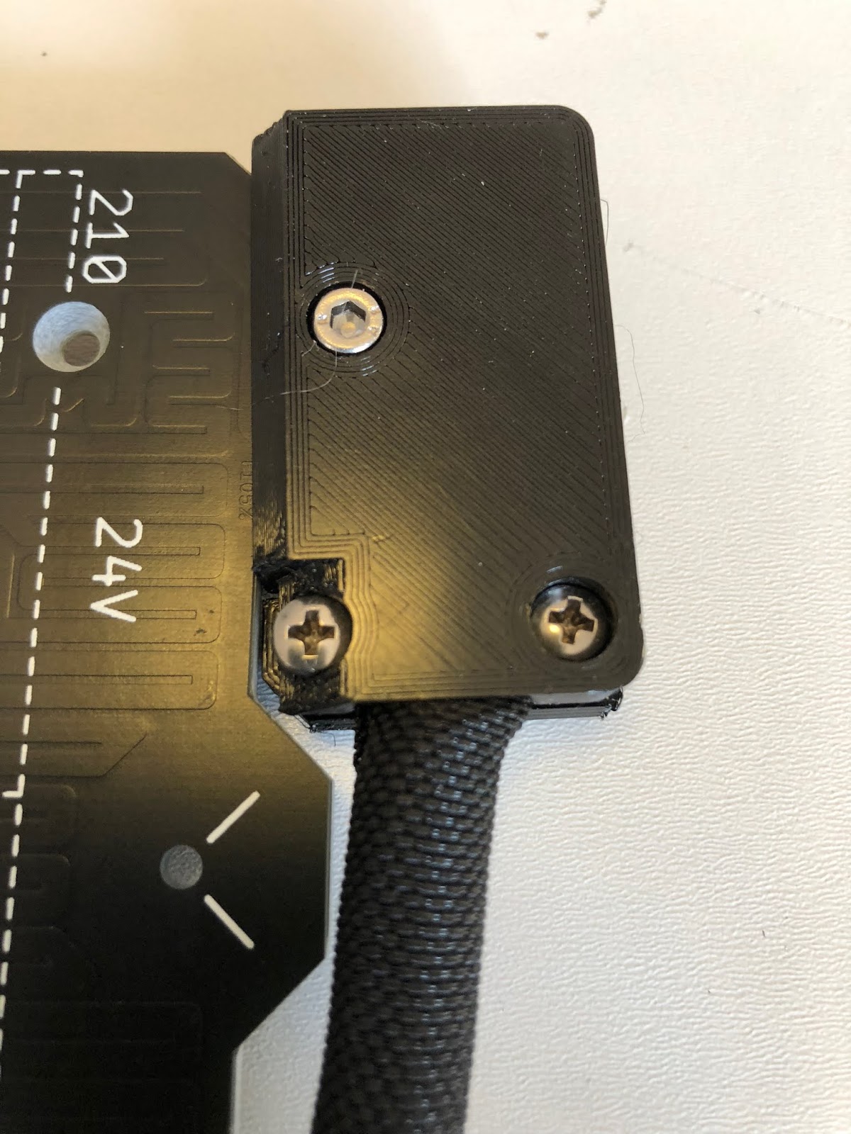
So I started to assemble the heat bed. As you can see the MK52 klon has soldered wires. I would have preferred the version with screw on cables. I 3D printed the cable cover with a 90° angle as this MK3 klon is supposed to go into an Ikea Lack enclosure. Then you need the stand offs with counter sunk screws, 2 M3x12mm, 1 M3x10mm and 1 M3 nut. If you wonder about those pliers, both ends move parallel and I like to use them to press in nuts in 3D printed parts. So you don't tilt them.


The cover is secure with a M3x10mm screw to the heat bed. I use the cable sleeves that Prusa recommends now. Also make sure you align the cable from the temperature sensor properly.

When everything is in place secure the cable with the clamp.


This is how the cover looks on the top side.


Now you can mount the heat bed with the stand off and screws to the y-carriage. Once you are done it should look like this.


The other parts I printed are for the Einsy Rambo case. The case, door, hinges and cable clamps.
In the last minute I decided to go with the latest design from Prusa that has an option to easily access the Raspberry Pi zero.


With some sharp pliers and a deburring tool you can nicely remove the area for the Pi.


Then you need to press in the 4 M3 square nuts and the 4 normal M3 nuts. Then it is time to secure the Einsy Rambo board with 4 M3x10mm screws.


Before we can proceed we need to attach a cable sleeve to the x axis stepper motor. I had something lying around that I secured with a cable tie to the motor.


Then you just have to assembly the door with the hinges to the frame and finally the case with the board. Make sure you don't forget to feed the cable sleeve from the x-axis thru the hole in the case, before you screw it to the frame. Then attach the Pi cover.


The X and Z axis assembly and Chinese precision

Now that I had all parts here, I could also finish the x axis. I already assembled both x ends in a previous step and put the nuts from the lead screws on them. All I needed then was the 3 LM8U bearings and the original 3D printed x-carriage, 850mm of GT2 timing belt, the two 370(!)mm steel rods and 2 cable ties.
Again I recommend to follow the instructions from Prusa:

Prusa X-axis assembly

Prusa Z-axis assembly

If you wonder why I use the standard 3D printed x-carriage now, and not the CNC aluminium part. Then look into the hot end part 2 post, I explain there in detail that the mont only works for the Titan extruder or Titan Aero hot end, but not for the Titan Aqua.
But I am going to use the Titan Aqua and also not a standard V6 hot end. For more details wait for the next hot end part.


Frist, carefully slide the bearing over the two steel rods and make sure you don't push out any balls from the bearing. The steel rods slide into the aluminium parts and are secured with set screws.


On the x-carriage you first need to press in 4 square M3 nuts.


Then prepare the cable ties in the x-carriage.


As next you can seat the bearings in the x-carriage and secure the upper ones with the cabe ties.


So far so good, I thought. But when I tried to assembly the x-axis to the z-axis I noticed that the lead screws were bending away from each other. With the z-axis tops you can see that there is a huge offset.


So I took the x-axis off again, secured both lead screws with the z-axis tops and took some measurements. I know, a folding rule is not an exact tool, but that was in reach.
The distance between the two lead screws was 332 mm.


The I measured the distance between the lead screw nuts in the x-axis and it was 340 mm, 8mm more.


Then I checked if the holes in the CNC parts were deep enough.


Everything looked ok, so I measured the steel rods. And gotcha. According to Prusa they should be 370 mm, mine were 374 mm. And I guess the other 4 mm are caused somehow by the CNC parts.


I need to cut off 8 mm off both stell rods and my tool of choice was my Dremel tool with a steel cutting disc. Surprisingly I was able to cut off exactly 8 mm off both steel rods with a decent looking cut and ended up with the same length for both steel rods.
I only needed deburring the ends and was able to put the x-axis together again.


Now the z-axis tops fitted perfectly, so I inserted the z-axis steel rods and mounted the tops on both sides. Just the little set screws to secure the steel rods on the z-axis were missing, but I noticed that already when I got the CNC parts. 


New Parts and the Y-axis assembly

On my first order one of those U-bolts was missing. The dealer promised to sent a spare one, but now after 3 weeks I still don't have it.


Meanwhile I ordered those bearing mounts made out of aluminium from Aliexpress, and they came in today. They come with the bearings inside. The 1.5mm allen wrench was not included, but you need it to properly align and secure the bearings. The big advantage of those is that if you tighten the U-bolts too much, you might ruin your bearings. This cannot happen with those.

Y axis aluminum Bearing holder  €15.31


As you can see on the image they have a little set screw to secure the bearing in the housing. You need to make sure the ballbearings inside are properly aligned to carry the load of the Y-xarriage. Don't over tighten the set screws as you might either damage the bearings or the threads in the aluminum part.


Now that I do have all parts for the Y-axis I recommend to follow the excellent instructions from Prusa for the assembly. Prusa Y axis assembly As I already put the frame together in an earlier post I can skip the first part. So what we need is the Y-carriage, the bearing with the mounts with 6 M3x10mm screws and the clamp for the timing belt with 2 M3x8mm screws.


We start with the mounts for the bearings. Do not tighten them yet! And as you can see, I made sure I can access the set screws from the side. And the open side of the belt clamp must face towards the side with the two bearings.


Then you need to carefully insert the 330 mm steel rods into the bearing. Don't tilt the rods and try to insert them as straight as possible. Otherwise you might push out some balls from the bearings.


Before we can mount them on the printer we have to remove the aluminum mount for the rods. They are not made for snap-in as the 3D printed parts. Don't even try it, you will just ruin you steel rods. For the it was enough to losen them on only side and remove them completely on the other side.
The you should be able to slide mounts on the steel rods and the steel rods in the mounts on the other side. Again, don't tighten anything yet!


The next step is to align the Y-axis. As you can see on the picture below there is just very little place between the mounts for the bearings and the frame. First, tighten the little set screws in the mounts for the steel rods. Don't use a lot of force and tighten them equally on both sides.
Move the Y-carriage to one side and tighten the mounts for the steel rods. Then move the Y-carriage to the other side and tighten the mounts for the steel rods there as well. The last thing to do is to tighten the mounts for the bearings. Now make sure the bearing mounts to not scratch over the frame when you move the y-axis assembly.


The next step is to install the GT2 timing belt. You need to cut a length of 650mm with some good scissors.

Follow the instructions from Prusa to assembly the belt. I need to make sure I loosen up the belt tensioner. I also needed to loosen those 3 Philips screw on the clamp to get the belt in.


Once the belt was in place I could tighten the screws and use the belt tensioner to adjust the belt tension.


I double checked the tension on the belt by holding the stepper motor with some pliers and trying to move the Y-axis. Again, do not over-tighten the belt as it will pull down the Y-carriage and bend you steel rods.

Sunday, December 9, 2018

The Hotend part 2

Finally the Titan Aqua klon arrived. It was well packaged and included all required parts.


So it was time to put the x-carriage together as well. Be aware that for this one you need two LM8LUU (45 mm long) bearings and not three LM8LU (24mm long) bearing as in the original Prusa X-carriage. You will need also those special pliers to secure the bearing with the secure lock washers.


Once everything is in place it should look like this. As You can see I made some scratches to the ionized surface with my cheap pliers.


So in the moment of truth I recognized then that this mount is not usable for the Titan Aqua. It just won't fit. Not matter what you try. So now I have not much options left. I could try to mill the carriage to make it fit, but that is not as easy as it sound. Or I 3D print a new mount. I need to come up with a solution for the PINDA probe anyway.


As it is designed for a Titan Extruder and the Titan Aero is not much different from the Titan Extruder, and because I have an original E3D Titan Aero laying around here, I tried this one.
And it fits perfect. So I could just go with the Titan Aero as an alternative, but the goal was to use a Water cooled hotend.


Saturday, December 1, 2018

The Hot End with Water cooling and the Fan Problem Part 1

As I have decided to use an Titan Aqua Klon instead of a standard E3D V6 Klon, this creates some problems.
Before we start I should mention that all fans on the MK3 are running with 5V, not 24V.

Let us start with the Parts list:

Titan Aqua Klon for 1.75mm 24V with NTC €63,63
120mm Radiator €13,62

50x140mm Water Reservoir €10,19

PWM Water Pump with Tacho signal  €13,62

Besides that I will need some tubing, pneumatic fittings and a 120mm silent fan(noctua).

Tests will show if the radiator and the water reservoir is big enough or if I need to increase them.

The blower fans I bought are useless to me unless I want to turn the monitoring function in the software off. Those are advertised as MK3 parts, but have no tacho signal. You need a 3 pin version for the MK3.
2x Blower Fan 5V €3,89 (Don´t buy these!)

But those are hard to come by. I have not found one in Aliexpress or ebay for cheap, so I am going to order this fan from Prusa. Yes, that will be the only original part on my built.
Strange that I found the Einst Rambo board, the filament sensor and the P.I.N.D.A probe, but cannot find a 5V radial blower 3 pin fan with tacho signal.

Original Prusa Print fan with tacho signal €7,27

But I will keep looking into this, maybe I can find another source. I you know a source leave a comment below.

Before we go into details I would like to explain why a tacho signal is important. I read quite often that a fan failed on a 3D printer.  For example if you have a lot of stringing and some filament string get into the hot end fan and block it. So what can happed is that the whole hot end get to hot then, not just the heat block. And maybe you habe a 3D printed mount for your hot end, which might work fine in normal condition when the heat sink of the hot end is cooled down by the fan.
But if this fan fails, the disaster takes its course and quickly the shit hits the fan. This could be the how some of the fires caused by 3D printers started.
Luckily Prusa monitors the fans with the tacho signal and turn the heat element off when the fan has a problem. If this is required for the print cooling fan as well or just for the hot end cooling fan is arguable. But Prusa monitors both.

So for my water cooling I have the following problem. There is no fan to cool down the hot end, that is done by the water cooling. But what if the water pump fails? What about the missing tach signal form the fan?
Sure, I could simply remove the fan monitoring feature in the firmware, but I consider this as an important security feature.

My Water pump is a 12V PWM controlled, so we have 4 pins (Vcc, Ground, Tacho, PWM). The Hot end cooling fan is a Noctua NF-A4x10 5V with only 3 pins (Vcc, Ground, Tacho).

So first problem is that I have a 5V signal form the Einsy Rambo board that usually powers up the hot end fan. My Water pump is 12V and needs for sure more power then the little fan.
The solution is quite easy, I will use a MosFET that is triggers by the 5V from the board and switches the 12V for the pump. OK, I could also just use a "normal" switch and switch the pump on/pff manually. But hey, where would be all the fun in the built?
What about the PWM? According to the specifications of PC mainboards, the pump should run always a full speed when there is no PWM signal. We will find out if this is true once the pump has arived.

For the next problem we have to understand how the tacho signal works. In fans with tacho signal there is a high sensitivity hall-effect sensor that detects the rotation of the shaft providing with two pulses per rotation, where the north pole generates a positive pulse and the south pole a negative pulse. The output of the hall sensor is usually weak and not a square wave. So a differential amplifier amplifies it, and a Schmitt trigger provides the switching hysteresis to reshape it into a TTL (5V) square wave.
As my water pump was designed to be used in PC´s I assume that the output tacho signal is 5V as well, even the pump runs at 12V. So in theory there is nothing I have to perform on the tacho signal. I will confirm once the pump has arrived.

One thing I am thinking of adding is a small fan controller with a temp sensor. The sensor will be added to the cooler and controls the fan speed of the 120mm water cooler fan based on the water temperature. The fan I am planing to use is the 120mm Noctua NF- F12 as this fan is optimized for radiators.
And of course I need to design and 3D Print a mount for the radiator that fits to the Ikea Lack enclosure.

For the print cooling fan there is not much todo, except to design a mount to attach it to the Titan Aqua klon somehow.



Wednesday, November 28, 2018

New parts arrived and MMU Part 3

So today more of the parts arrived that I ordered for my built.

Finally I have the stepper motors. Pro Tip, whatch out for those with the lead screw as shaft, don't use the cheap ones with couplers. So I was about to finish the frame built today...


But I realized that the M3x10mm don't fit as the aluminium parts are not as thick as the original 3D printed Prusa parts and the screws don't fit far enought into the motors to be tight. So I ordered some M3x8mm as I don't have them in stock.

Then I got some of the MMU 2 parts today. I have not the stepper motors.


The MMU 2 electronic board came with cables. Also the 2x4mm orange PTFE(the usual PTFE tubing used for 3D printers has a smaller inner diameter than 2mm) with push fittings.
And the two shafts with brass tubes as bearings for the selector.


I am still waiting on the bearings and I need to get the 2 springs for the MMU 2. I could order them from Prusa, but the goal was to het everything as cloned parts. Then I still need to print the idler in PC. But printing PC is tough without enclosure.

I also got the 5x16mm shafts for the idler today.


I was so eager to put things together that I just started with the selector and put the electronics board into the chassis.

For the electronics board you just need 3 M3 nuts, 3 M3x6mm screws.


The nuts are pressfit into the 3D printed part. The electronics board is inserted. Watch out for the micro USB port and the switches. Then secure the board with the 3 screws. Don't tighten then too much, otherwise you night damage the board.


For the selector you need 6 M3x10 screws, 1 M3x18 screw, 6 M3 square nuts and 1 M3 nut.
And the front plate, the lead screw nut and the blade.


Prusa has a very good manual how to put it together.
Prusa MMU assembly

Once you are done, it should look like this. Be careful when you handle it as you can easily but yourself with the blade sticking out.


A new project "automatic cat litter box"

 I did not post any updates for a long time. I spent some time making some money with 3D printing to recover some of the costs from this hob...